Creating a Whole Home Water Meter with ESPHome
8/28/2025
7 min read
In my last post I got energy data into my home assistant but left off with wanting to get water data into the system to monitor water usage. In this post, I'm going to explain how I got it working and some of the pitfalls I ran into along the way.
So if you haven't read my last post, you should read it to understand a bit about the "Energy Dashboard" in Home Assistant.
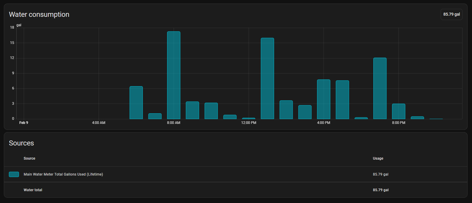
The goal of getting water metering working is being able to see how much water we're using hourly and produce a dashboard like this:
§Buy vs Build
There are a few commercial products on the market that just work. They all require a cloud connection and some sort of subscription. They work pretty well but they can be pretty pricey to buy and you're still beholden to their cloud services.
The goal of my Home Assistant setup is to get as much off of the cloud as possible, plus... what's the fun in just buying something that already works when we can build our own solution that is fully local?
§What We Need
We will need a few things to make this work.
- A way to meter the water flow
- A way to read the meter and send it to Home Assistant
- A will to troubleshoot
§A Way to Meter the Flow
First we need a way to meter the water. I did a bunch of research and ordered a few options from Amazon.
The first thing I learned is that almost all the meters I could find were BSPT (British Standard Pipe Thread) which is NOT COMPATIBLE WITH AMERICAN NPT. You will need adapters (more on that later).
The first meter I purchased was made of plastic and was made by Gredia. You can find it on Amazon here. This was the WRONG option. The plastic was terrible and it had a catastrophic failure when pressurized. It's not meant for real water main pressure. It's more for automated systems that need to meter fluid flow like assembly lines or transfer systems.
This led me to the Brass version which can be found here. This is the one you want!
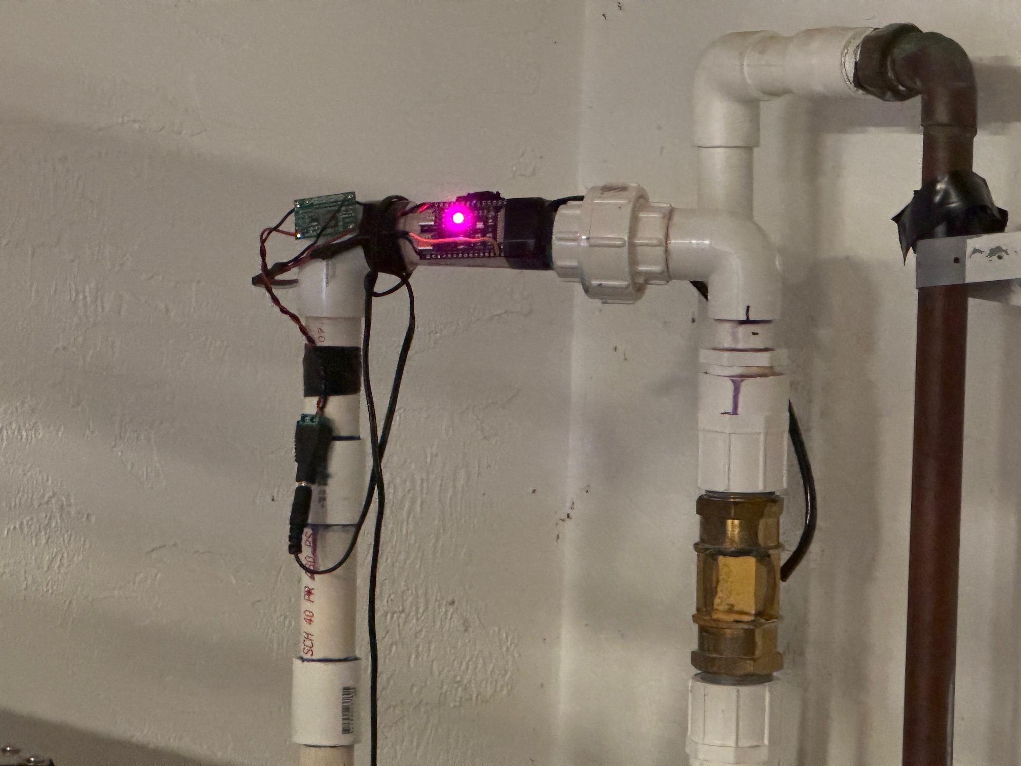
Now you just need to plumb the meter inline to your water main and make sure you have the water moving in the same direction as the arrow on the housing. (It's probably a good idea to hire a plumber for this. I didn't and I flooded my garage because of it. yay)
§BSPT Woes
So all the options I found were all BSPT and that feels like it works with NPT but it does not. It will catastrophically fail. Without a doubt. I found these adapters on Amazon to interface with NPT PVC that I plumbed inline to my water main inside my house. For the keen eyed, you'll notice that one of these adapters is more than the cost of the meter itself and you need TWO of them. yea.. kinda sucks. But this is how DIY goes right? More expense and more time to get something subpar to the commercial options. lol.
The biggest gotcha here is that the o-ring isn't enough for water main pressures. You need to give it the belt and suspenders treatment and use a healthy amount of teflon thread tape to backup the o-ring. Trust me, it's a hard learned lesson.
§A Way to Read the Meter
So I considered many options but Home Assistant supports ESPHome so a simple little ESP32 dev board works well. The trick here is that the water meter needs 5vdc and uses 5v logic, but the ESP32 only tolerates 3.3v logic.
§ESP32 Wiring
The first thing we need to do is wire up something that can provide 5vdc to the meter and the ESP32 development board and something that can step the 5v logic down to 3.3v for the ESP32 to process.
I had some buck converters in my bin (you can find them here) and I have it outputting 5vdc from a 12vdc power supply.. but you can use whatever to provide 5vdc.. there's many options.. even USB! You can even use the 5v pin on the dev board and use the USB on the board to supply it.
This is the ESP32 I used
For the logic level shifting, I just used a simple MOSFET setup. I Dug around in my bin of misc MOSFETs and found a 2N7000... perfect!
This is how I wired it up:
Sensor (Yellow) -- 10kΩ --+--> ESP32 GPIO40
                          |
                          |
                      Gate of MOSFET
Drain --> ESP32 GPIO
Source --> GND
Pull-up to 3.3V on ESP32 side
Pull-up to 5V on Sensor side
So the final wiring of the setup is super simple:
5v                    --> RED Wire on the Meter
Meter Signal (yellow) --> 1kΩ (limiter)    --> MOSFET Gate
GND                   --> MOSFET Source
GPIO40                --> MOSFET Drain
3.3V --> 10kΩ (pullup) --> MOSFET Drain§ESPHome Configuration
After setting up ESPHome on the ESP32 through Home Assistant I used ChatGPT to calculate the pulse rate using the information provided in the listing from Amazon. After some back and forth and testing.. it turned out to be:
(pulses + 4.0) * 0.0352229;This resulted in the following Sensor Config in ESPHome:
sensor:
  - platform: pulse_counter
    pin:
      number: 40
      inverted: true
      mode:
        input: true
        pullup: true
    name: "Water Flow GPM"
    device_class: water
    unit_of_measurement: "gal/min"
    accuracy_decimals: 2
    update_interval: 1s
    id: water_flow
    total:
      name: "Total Gallons Used (Lifetime)"
      device_class: water
      state_class: total_increasing
      unit_of_measurement: "gal"
      filters:
        - lambda: |-
            if (x < 0.1) return 0.0;
            float hz = x / 60.0;
            return (hz + 4.0) * 0.0352229;
    filters:
      - lambda: |-
          if (x < 0.1) return 0.0;
          float hz = x / 60.0;
          return (hz + 4.0) * 0.0352229;
A few things to note here is that we are setting a lifetime gallons which is REQUIRED for the energy dashboard to work properly.. and then I'm also calculating the GPM for my own dashboards which we'll see later.
The fine tuning and validation was done by actually running a faucet into a 5 gallon bucket and timing it to full fill and then verifying that the data logged match the GPM that I calculated.
§Setting up the Dashboards
Once this is sending data to Home Assistant, you just need to grab the lifetime number and tell it to use that on the Energy Dashboard:
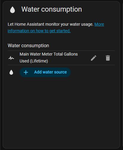
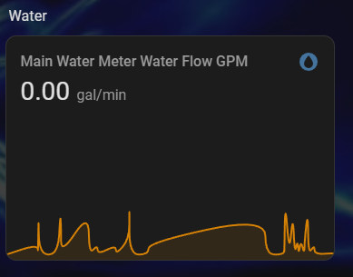
If you're like me and want a more realtime dashboard you can use the GPM to put a graph on any dashboard.
§Extras
One of the things I thought would be a nice extra touch was to use the dev board's onboard RGB LED to indicate when water was flowing.
So I decided to use purple to show that the water isn't flowing and blue to indicate that the water is moving and we're consuming water.
I added an on_boot to turn the LED Red to show the MCU is booting. And then I change to purple or blue on an interval.
esphome:
  name: main-water-meter
  friendly_name: Main Water Meter
  on_boot:
    then:
      - light.addressable_set:
          id: status_led
          red: 100%
          green: 0%
          blue: 0%

sensor:
  - platform: pulse_counter
    pin:
      number: 40
      inverted: true
      mode:
        input: true
        pullup: true
    name: "Water Flow GPM"
    device_class: water
    unit_of_measurement: "gal/min"
    accuracy_decimals: 2
    update_interval: 1s
    id: water_flow
    total:
      name: "Total Gallons Used (Lifetime)"
      device_class: water
      state_class: total_increasing
      unit_of_measurement: "gal"
      filters:
        - lambda: |-
            if (x < 0.1) return 0.0;
            float hz = x / 60.0;
            return (hz + 4.0) * 0.0352229;
    filters:
      - lambda: |-
          if (x < 0.1) return 0.0;
          float hz = x / 60.0;
          return (hz + 4.0) * 0.0352229;

light:
  - platform: esp32_rmt_led_strip
    rgb_order: GRB
    pin: GPIO48
    num_leds: 1
    id: status_led
    rmt_channel: 0
    chipset: ws2812
    name: "Status LED"

interval:
  - interval: 1s
    then:
      - if:
          condition:
            lambda: "return id(water_flow).state > 0.1;"
          then:
            - light.addressable_set:
                id: status_led
                red: 0%
                green: 0%
                blue: 35%
          else:
            - light.addressable_set:
                id: status_led
                red: 50%
                green: 0%
                blue: 25%
And adding a bit electrical tape to "mount it" and we're done here!